GTRC Gas Mixing Facility
Due to the requirement for combustor flexibility, the centre employs a multi-line gas mixing facility. Each supply is fed from the external fuel storage compound, with independent Coriolis mass-flow measurement and proportional valve control.
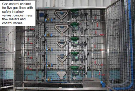
Fuel Control Valves and Flow Measurment
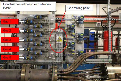
Fuel Inlet Manifold
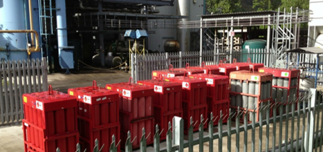
Fuel Storage Compound

Copyright 2007-2020 Cardiff University - Gas Turbine Research Centre :: Privacy Policy :: Terms of Use